


 Phan Van Hoang
- 05/08/2026
- 150
When a bag sewing machine repeatedly breaks thread, produces seams that alternate between tight and loose, or requires repeated tension adjustment during a shift, operators often suspect thread quality, the needle, or the tension unit. However, one easily overlooked cause is a thread path that is too long, incorrectly positioned, or has excessive deflection angles.
The tension experienced by the thread at the needle is not determined solely by the two tension discs. It is the combined result of the thread unwinding from the spool, passing through each guide eye, spring, thread take-up lever, tension unit, needle eye, and stitch-forming area. Research on industrial sewing machines shows that during a sewing cycle, the thread is continuously affected by guides, tension discs, tension springs, the take-up lever, the needle eye, and the material being sewn. Therefore, even one incorrect point along the thread path can significantly change the actual tension at the needle.
It is important to understand that a long thread path does not always significantly increase average tension. If the thread travels almost straight, without rubbing against surfaces or creating additional contact points, the effect may be small. Problems arise when a long path is combined with multiple guides, large direction changes, excessively long free-thread sections, or misaligned guides.
Table of Contents [Hide]
1. What components make up the thread path on a bag sewing machine?
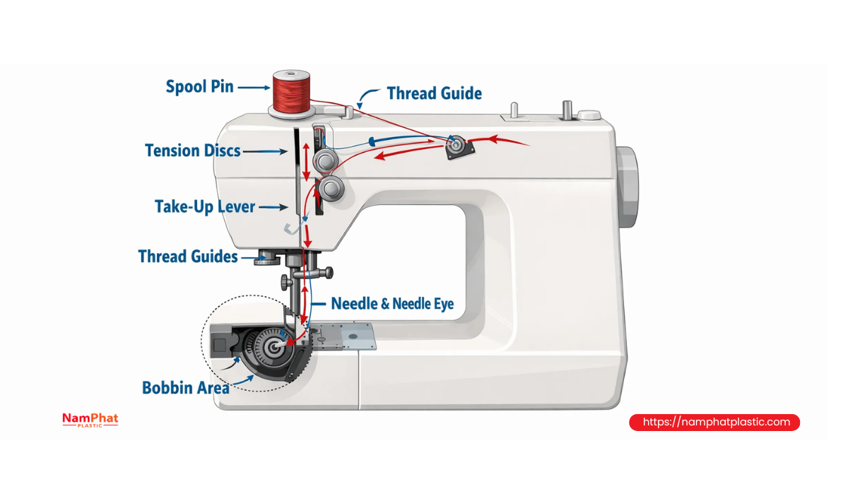
Depending on the configuration of a single-needle, two-needle, single-thread, or two-thread machine, the exact path may differ. However, a typical bag-sewing thread path includes:
-
Thread spool or cone.
-
Spool holder.
-
First guide eye above the spool.
-
Intermediate guide bars and guide eyes.
-
Tension discs.
-
Thread-control spring.
-
Thread take-up lever or thread feeding/take-up mechanism.
-
Guide eye near the needle bar.
-
Needle eye.
-
A separate looper-thread path on two-thread machines.
Each component has a specific function. Some guides stabilize thread unwinding; some establish the correct direction before the thread enters the tension unit; others work with the needle and looper movement to provide the correct amount of thread at each stage.
Therefore, guide eyes should not be removed or the thread path changed simply because the current path appears to be “too winding.” Union Special technical documentation requires the thread to be routed correctly through the tension unit and guide eyes; incorrect threading can cause distorted stitches.
2. Why does the thread-guide angle change thread tension?
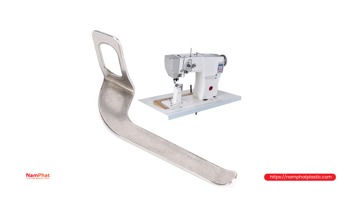
When thread changes direction around a guide eye, it creates a contact force against the surface. The resulting friction resists thread movement, causing the pulling force on the outlet side to differ from the tension on the inlet side.
This relationship can be approximately described by the capstan-friction equation:
-
T₂ = T₁ × e^(μθ)
Where:
-
T₁ is the tension before the contact point.
-
T₂ is the tension after the contact point.
-
μ is the coefficient of friction between the thread and guide surface.
-
θ is the total wrap angle around the surface, expressed in radians.
The equation shows that tension does not simply increase linearly; it depends on both friction and contact angle. The greater the direction change and the more the thread wraps around the guide, the greater the tension difference before and after the contact point. The angle-dependent friction mechanism is also used in research models of thread tension and thread slippage during stitch formation.
In practice, if the thread only glides lightly through the center of a smooth ceramic guide, resistance is relatively stable. But if a misaligned guide causes the thread to press against an edge, contact angle and localized pressure increase. The tension can then rise suddenly even though the operator has not adjusted the tension knob.
3. How does an excessively long thread path affect tension?
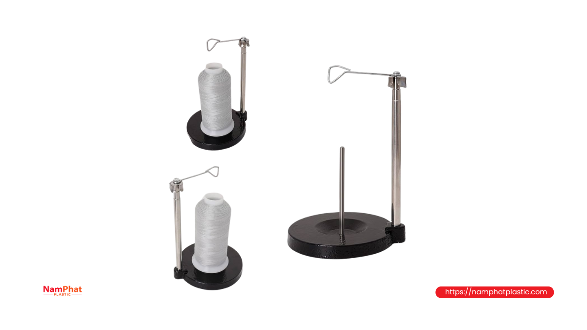
3.1. Increasing the number of friction points
The longer the path, the more intermediate guide eyes are often required. Each additional contact point adds some resistance. If all guides are clean, smooth, and correctly aligned, the increase may be small. But a single worn, dusty, or scratched ceramic guide can become a source of abnormal tension.
The total resistance of the thread path does not depend on one guide alone; it is the accumulated result of multiple contact points. Therefore, loosening the tension knob may not solve the problem: nominal tension at the tension discs decreases, but the thread may still be restricted by a guide before or after the tension unit.
3.2. Creating free-thread sections that vibrate and form “thread balloons”
When the distance from the spool to the first guide or between two guides is too large, the thread can oscillate laterally while the machine is running. At low speed, the effect may be difficult to notice. As speed increases, the free thread section can form a rotating loop or “thread balloon” around the spool.
The size of the balloon continuously changes according to:
-
Unwinding speed.
-
Remaining spool diameter.
-
Thread stiffness.
-
Winding uniformity.
-
Distance from the spool to the first guide.
-
Spool orientation relative to the first guide.
As the balloon expands, pulling force may briefly decrease. As it contracts or contacts the spool body, tension can suddenly increase. The result is unstable tension from cycle to cycle, producing alternating tight and loose stitches.
3.3. Increasing the chance of thread catching on surrounding equipment
A long thread path often crosses several areas of the machine frame. If poorly arranged, the thread may touch:
-
Spool support bars.
-
Machine-frame corners.
-
Electrical cables or air hoses.
-
Cover edges.
-
Adjacent thread spools.
-
Excess thread from another position.
These contact points may not occur continuously. The machine may run normally for several minutes and then suddenly break the thread, making the cause difficult to identify.
3.4. Increasing delay during thread feeding and take-up
Synthetic thread has a certain degree of elasticity. A long thread path behaves like an elastic storage section: when the take-up lever pulls the thread, part of the movement is used to tension the long thread section before the force is fully transmitted to the needle area.
When the take-up lever moves down, some of the stored energy may be released, temporarily creating excess thread. This can make the system respond more slowly, especially when:
-
The machine runs at high speed.
-
The thread has relatively high elongation.
-
Tension is set low.
-
The path contains multiple uncontrolled long sections.
-
The take-up lever or thread-control spring is incorrectly adjusted.
The result is not necessarily excessively high average tension, but rather a larger amplitude of tension fluctuation.
3.5. Creating tension differences between threads
On two-needle machines or machines using multiple thread paths, if one spool is positioned closer to the machine than another, the two threads experience different friction and vibration conditions.
Even if both tension knobs are adjusted by the same number of turns, the actual tension at the two needles may differ. One seam may be tighter, while the other thread may form larger loops or be more prone to skipped stitches.
Therefore, on multi-thread machines, try to maintain:
-
Relatively similar thread-path lengths.
-
Similar numbers of guide points.
-
Similar direction-change angles.
-
The same type of contact surfaces.
-
Similar thread-unwinding conditions.
4. What problems can an incorrect thread-guide angle cause?
4.1. Thread rubbing against the edge of a guide eye
Thread guides are normally designed for the thread to travel near the center. When a guide is rotated, bent, or misaligned, the thread can run close to one side of the guide wall.
At the contact edge, pressure is concentrated over a small area, causing:
-
Increased friction.
-
Thread-surface heating.
-
Fiber abrasion or partial filament breakage.
-
Thread dust.
-
Wear grooves in the guide.
-
Random thread breakage.
With PP or PE filament thread, the thread may not break immediately. Some outer filaments may be scratched first, making the thread surface fuzzy or reducing its load-bearing capability. The thread may then break at the needle eye or when the stitch is tightened.
4.2. Thread entering the tension discs at an angle
Tension discs work most effectively when the thread enters the working area correctly and is evenly clamped between the two disc surfaces. If the thread enters at an angle, it may:
-
Contact only part of the disc surface.
-
Run close to the shaft or disc edge.
-
Fail to remain completely between the discs.
-
Be clamped unevenly as the machine vibrates.
-
Slip out of the tension unit.
As a result, a small adjustment of the tension knob may cause a disproportionately large change in tension, or almost no change at all. Operators may feel that the tension unit is “not responding,” while the actual cause is the thread direction before it enters the discs.
4.3. Thread pulling the spring or take-up lever sideways
The thread-control spring and take-up lever are designed to receive force in a relatively defined direction. If the thread pulls sideways, the component may experience lateral friction, respond slowly, or fail to return consistently.
Common consequences include:
-
A thread loop at the needle that is too small.
-
Difficulty for the looper to catch the thread loop.
-
Random skipped stitches.
-
Strong thread pulling at the end of the cycle.
-
Alternating tight and loose seams.
-
Faster wear of the thread-control spring.
4.4. Thread entering the needle eye from the wrong direction
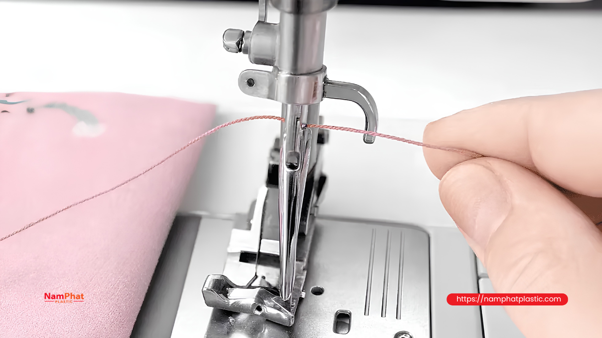
The final guide eye directs the thread into the needle eye from the correct direction. If this final guide is misaligned, the thread can be pulled toward one side of the needle eye.
During operation, the thread repeatedly rubs against one edge of the needle eye rather than distributing contact evenly. This can cause:
-
Rapid thread heating.
-
Surface abrasion.
-
Filament separation.
-
Thread breakage near the needle.
-
Unstable thread-loop formation.
In this case, installing a new needle may temporarily improve operation. However, if the thread-guide direction is not corrected, the new needle will continue to experience off-center loading and the problem will return.
5. How does an incorrect thread path affect bag stitches?
For a two-thread chain stitch, the needle and looper must receive the correct amount of thread at the correct time. Union Special documentation indicates that needle-thread tension should be sufficiently light to maintain the appropriate loop at the needle, while the amount of thread supplied by the control mechanism should be just enough to form the required needle loop. This shows that stitch quality depends not only on the tension setting but also on the ability to feed and take up thread at the correct time.
When the thread path is too long or incorrectly angled, one or more of the following may occur:
Stitches that are too tight
The thread experiences increased friction before reaching the needle, causing the stitch to tighten more than expected. The bag mouth may wrinkle, contract, or become cut at needle penetration points.
Bag-sewing machine manufacturers also note that appropriate low thread tension helps reduce thread-breakage risk, while excessive tension can damage the material around the seam.
Stitches that are too loose
If a long thread path creates vibration or the spool releases thread intermittently, the machine may receive excess thread at certain moments. The thread can form large loops, resulting in loose stitches, an uneven chain, or a seam that can easily pull apart.
Alternating tight and loose stitches
This is a typical sign of unstable dynamic tension. Loosening or tightening the tension knob may change the average level but does not eliminate the fluctuation.
Random skipped stitches
When tension suddenly increases, the loop behind the needle may become too small for the looper to catch. Skipped stitches may occur irregularly, especially when the machine accelerates or the spool is nearly empty.
Thread breakage at inconsistent locations
If the thread is damaged by friction at a guide, the weakened section may travel toward the needle before breaking. Therefore, the location where the broken thread is found is not necessarily the location where the damage originated.
6. Signs that the thread path has a problem
| Observed phenomenon | Thread-path-related cause |
| Machine runs normally at low speed but breaks thread when speed increases | Excessively long free-thread section, excessive vibration, or high resistance caused by guide angles |
| Thread becomes fuzzy on one side | Thread is pressing against a guide edge or one side of the needle eye |
| A new spool runs well but frequently breaks when nearly empty | Unwinding angle and thread-balloon behavior change with spool diameter |
| Tension knob must be loosened significantly before the machine runs properly | Resistance is being generated outside the tension discs |
| Tight and loose stitches alternate repeatedly | Tension fluctuation caused by thread ballooning or a vibrating long thread section |
| Two seams on a two-needle machine are uneven | Different thread-path lengths or numbers of guide points |
| Thread frequently jumps out of the tension discs | Thread enters the tension unit at an incorrect angle |
| Thread dust accumulates around one ceramic guide | Guide is scratched, worn, grooved, or has an excessive contact angle |
| Changing thread lots does not stop the breakage on the same machine | The problem is more likely in the thread path, tension unit, or needle than in the thread itself |
| Machine becomes stable only after reducing speed | The thread path does not adequately control dynamic tension |
7. What is considered a proper thread path?
There is no single maximum length that applies to every machine. Spool size, machine speed, thread construction, and tension-unit design all differ. A suitable arrangement should prioritize the following principles:
Keep the path short but functional
Use the shortest path allowed by the manufacturer's threading diagram, without unnecessary loops or detours. However, do not arbitrarily remove guide eyes that control thread ballooning, establish the correct entry angle into the tension discs, or coordinate with the take-up lever.
Use smooth direction changes
Avoid sharp thread bends through small guide eyes. When a large direction change is required, use an appropriate guide arrangement to divide the change into gentler angles, provided this matches the machine design.
The thread should travel through the center of the guide
Observe the machine at both low speed and production speed. The thread should not continuously press against one side of a guide eye.
The spool and first guide should be reasonably aligned
If the spool unwinds from the cone top, the first guide should be positioned so that the thread exits steadily without wrapping around the spool body or pulling strongly to one side.
Free-thread sections should not be excessively long
Large distances between control points increase vibration and fluctuation. When the spool holder must be positioned far from the machine, use an appropriate guide arrangement rather than allowing the thread to span a long uncontrolled distance.
Keep multiple thread paths equivalent
On multi-needle or multi-looper machines, thread paths should be reasonably similar in length, number of contact points, and direction-change angles.
8. Thread-path inspection procedure in the factory
Step 1: Disconnect the power before inspection
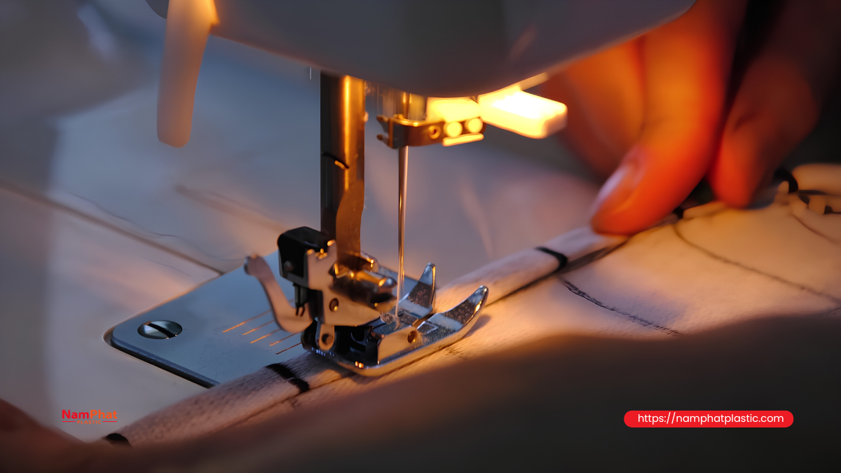
Turn off the main switch and wait until the machine has stopped completely before threading, removing the needle, or inspecting the guides. Industrial-machine operating documentation requires power to be disconnected when threading and performing maintenance.
Step 2: Compare with the threading diagram
Do not rely entirely on operator habit. Photograph or print the correct threading diagram for the specific machine model and place it at the workstation.
Check sequentially from the spool to the needle rather than starting from the needle and working backward, which can cause the first guide to be overlooked.
Step 3: Pull the thread by hand
Pull the thread slowly and relatively evenly. Check whether the pulling force:
-
Increases smoothly.
-
Jerks at certain points.
-
Becomes suddenly heavier at one location.
-
Produces rubbing or squeaking sounds.
-
Changes when the thread is gently moved sideways.
If pulling force changes significantly when the thread is shifted sideways, the guide may be misaligned or unevenly worn.
Step 4: Inspect each guide eye
Use angled lighting to look for:
-
Wear grooves.
-
Cracks.
-
Chips.
-
Metal burrs.
-
Clumps of thread dust.
-
Dried oil or contamination.
A soft piece of thread or fine cotton can be gently passed over the surface. If the material catches, the guide should be cleaned, evaluated, or replaced.
Do not use coarse sandpaper directly on ceramic guide surfaces because it can create roughness and accelerate thread damage.
Step 5: Observe the machine at low speed
Run the machine slowly and observe:
-
Thread-balloon shape.
-
Thread position within each guide.
-
Movement of the thread-control spring.
-
Movement of the take-up lever.
-
Vibration of free-thread sections.
-
Whether the thread touches the frame or adjacent spool.
Step 6: Check at production speed
A thread path may appear stable when the machine is turned by hand but become unstable at high speed. After ensuring the area is safe, test at the actual production speed.
Do not judge the result from only the first few stitches. Run long enough for the machine to reach operating temperature and for the spool to unwind continuously.
Step 7: Measure tension if equipment is available
If the factory has a thread-tension gauge, measure at:
-
After the first guide.
-
Before the tension discs.
-
After the tension discs.
-
Near the needle.
The objective is not only to measure average tension but also to observe fluctuation. A machine may have an acceptable average tension but still break thread or skip stitches if the fluctuation is excessive.
9. Adjustment sequence to avoid correcting the wrong cause
When a thread-path problem is suspected, proceed in this order:
-
Re-thread according to the manufacturer's diagram.
-
Reset the spool and spool-holder position.
-
Align the guide eyes so the thread travels through their central area.
-
Remove contact points that are outside the designed path.
-
Clean the guides and tension discs.
-
Replace cracked, grooved, worn, or burred guide eyes.
-
Check the needle, needle eye, and needle orientation.
-
Check the spring and take-up lever.
-
Adjust the tension knob only after the entire thread path is correct.
-
Test again at low, medium, and production speeds.
Adjusting the tension knob first can conceal the real cause. For example, if a guide is generating excessive resistance, the operator may loosen the tension unit to compensate. Once the guide is cleaned or the thread suddenly moves away from the rubbing edge, total resistance drops and the seam becomes too loose.
10. Should some thread guides be removed to reduce tension?
A guide should only be removed when it has been confirmed to be an unnecessary added component and removing it will not alter the machine's operating principle.
Original guide eyes may perform several functions:
-
Controlling thread ballooning.
-
Directing the thread into the tension discs.
-
Keeping the thread from leaving the spring.
-
Controlling the amount of thread supplied.
-
Forming the correct thread-loop size.
-
Separating needle and looper threads.
-
Preventing threads from crossing.
Union Special troubleshooting documentation notes that thread breakage can occur when threads cross each other, while distorted stitches may occur when the thread is not routed through the correct tension unit or guide eye. Therefore, taking a “shortcut” may reduce friction at one point while creating stitch-formation problems later.
11. Can additional oil be used to correct an incorrect thread path?
Thread finish lubrication helps control the coefficient of friction and supports machine sewability. Experimental research indicates that the type and amount of lubricant can significantly affect needle-thread tension; as the coefficient of friction decreases, thread tension can also decrease.
However, adding oil is not a solution for a misaligned guide, worn groove, or burr. Oil may temporarily improve machine operation but can also:
-
Change stitch stability.
-
Attract dust to guides and tension discs.
-
Cause uneven slippage.
-
Contaminate packaging.
-
Hide mechanical defects.
Correct the geometry of the thread path and contact surfaces first, then reassess the thread finish level.
12. Test procedure after adjusting the thread path
The factory can apply the following internal test:
Preparation
-
Use thread from the same lot.
-
Use the same needle type.
-
Use the same bag-mouth structure and number of layers.
-
Record the initial tension-knob position.
-
Clean the machine before testing.
Three test stages
-
Run slowly to observe thread movement and loop formation.
-
Run at normal operating speed.
-
Run continuously long enough to detect heat- and fluctuation-related problems.
Record
-
Number of thread breaks.
-
Location of fuzzing or thread damage.
-
Tightness or looseness of the seam.
-
Skipped stitches.
-
Wrinkling or tearing of the bag mouth.
-
Thread-balloon shape.
-
Difference between a full spool and a nearly empty spool.
-
Relative needle and thread temperature.
-
Average tension and tension fluctuation if a gauge is available.
Do not draw conclusions from only one or two bags. Thread-path problems often occur intermittently and become more obvious during continuous operation.
Frequently Asked Questions
1. Does a longer thread path always mean higher tension?
Not necessarily. A straight section without additional contact may mainly increase response delay and vibration. Tension rises more clearly when the long path adds guide eyes, wrap angles, rubbing points, or uncontrolled vibrating sections.
2. Can loosening the tension knob fix an incorrect thread path?
It may temporarily improve operation but does not correct the root cause. When resistance outside the tension unit changes, the seam may continue to alternate between tight and loose or break unpredictably.
3. Why does the machine often break thread when the spool is nearly empty?
As spool diameter decreases, the unwinding direction and thread-balloon shape change. If the first guide is poorly positioned, the thread may rub against the cone tip or core, or experience greater pulling force.
4. Does having more guide eyes make the thread more stable?
No. Each guide should have a clear function. Unnecessary guides add friction and create additional opportunities for wear, contamination, or misalignment.
5. Why does replacing the thread not stop the breakage?
If the cause is in the guide eyes, tension discs, needle, or thread direction, changing the thread lot only changes the severity of the symptom and does not eliminate the mechanical problem.
6. Should tension be adjusted separately for each spool?
A small adjustment may be necessary when thread construction or lots differ. However, if the same thread requires major adjustment every time the spool is changed, inspect the spool holder, unwinding angle, and entire thread path.
Conclusion
An excessively long or incorrectly angled thread path can increase friction, create tension fluctuations, impose uneven loading on guides, and disrupt synchronization between thread feeding and stitch formation. The result is often not simply “high” or “low” tension, but continuously changing tension depending on machine speed, spool diameter, and thread movement.
When a bag sewing machine breaks thread or produces unstable seams, do not focus only on turning the tension knob. Inspect the entire path from the spool to the needle, ensuring that the thread follows the correct threading diagram, passes through the center of the guides, does not make excessively sharp bends, and does not contain long, strongly vibrating free sections.
A correctly arranged thread path allows the tension unit to operate more accurately, reducing thread breakage, limiting skipped stitches, and maintaining stable seam quality throughout the production shift.
>>> See also:
- 0 Comment


