


 Phan Van Hoang
- 01/08/2026
- 147
When a thread spool cannot be installed onto the holder, the cause is usually identified quite quickly: the core hole is too small, the core is deformed, or the spool length exceeds the available space. However, a more difficult case occurs when the spool can be installed but is not positioned correctly.
The thread spool may sit at an angle, contact the support post at only one point, fail to reach the bottom completely, or vibrate slightly when the machine accelerates. These deviations may not cause the machine to stop immediately, but they can lead to thread tension fluctuations, thread rubbing, unstable unwinding loops, random thread breakage, or inconsistent seam quality.
Therefore, when evaluating a bag sewing thread spool, it is not enough to check only its weight, fineness, strength, and twist. Core dimensions, roundness, concentricity, and taper angle are also technical parameters that directly affect spool installation and thread feeding to the machine.
Table of Contents [Hide]
1. Not every thread spool that “fits” can be considered correctly installed
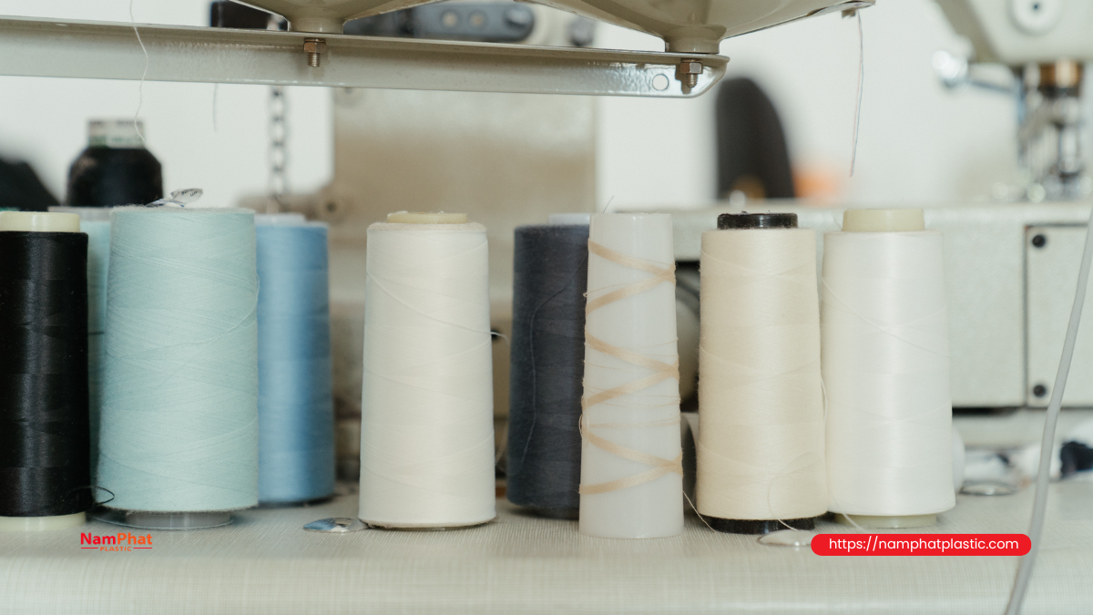
In actual production, operators often check a thread spool in a simple way: place the spool onto the post, and if it goes down, conclude that the core is suitable. This method is not sufficient.
A thread spool is considered correctly installed only when it meets all of the following conditions:
- The core slides onto the holder with normal hand force, without being hammered or forced.
- The spool reaches the correct operating position and does not remain suspended at the core opening.
- The spool axis is approximately aligned with the support-post axis.
- The spool does not visibly wobble or tilt.
- The core edge does not rub against the post, support disk, or thread-guiding components.
- The thread can be pulled in the intended direction without abnormal resistance.
- The spool remains stable at the actual production speed.
Therefore, “fits” only describes whether the core can be inserted onto the post. “Correct installation” also includes proper centering, stable support, and a suitable thread-unwinding path throughout operation.
2. Which core dimensions of a thread spool need to be considered?
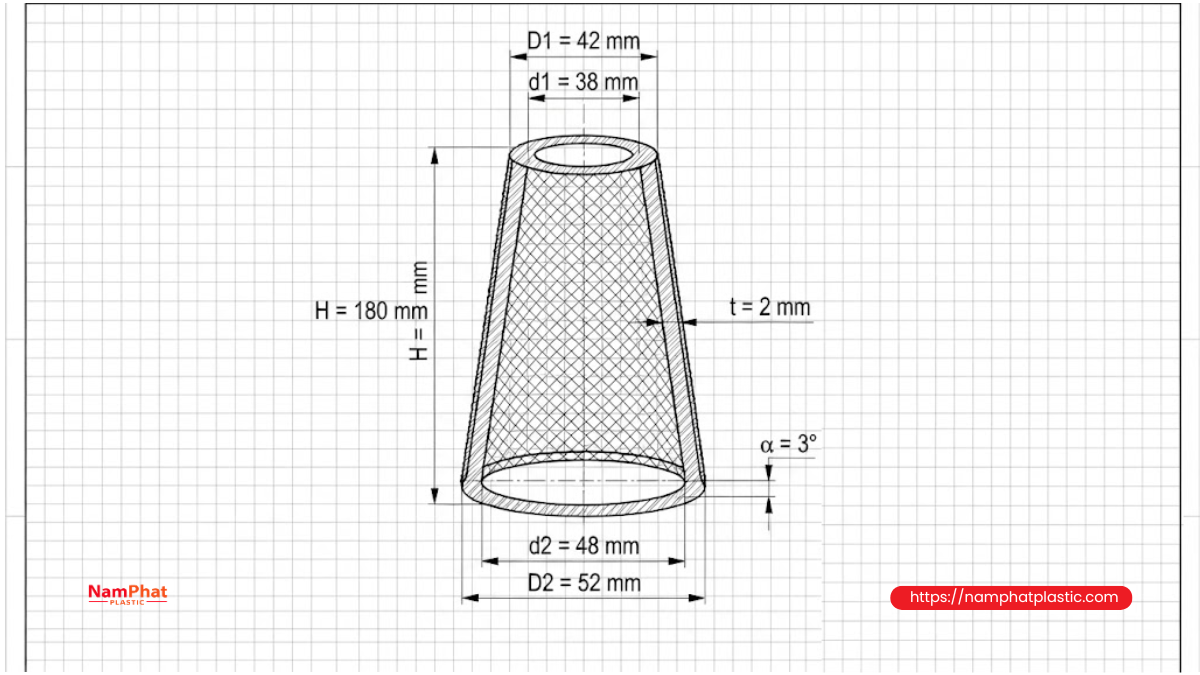
For a tapered core, the controlled dimensions should not be limited to a single hole diameter. A complete core drawing should specify at least the following:
| Reference | Parameter | Significance |
| H | Core length or height | Determines insertion depth and spool position on the holder |
| d1 | Small-end internal diameter | Affects initial core insertion |
| d2 | Large-end internal diameter | Affects insertion depth and stability |
| D1 | Small-end external diameter | Affects spool shape and thread-unwinding path |
| D2 | Large-end external diameter | Affects thread capacity and support on the disk |
| t | Core wall thickness | Determines stiffness and deformation resistance |
| α | Half taper angle | Determines compatibility between the core and tapered holder |
| — | Roundness, straightness and concentricity | Determines whether the spool tilts or runs out |
In addition to nominal dimensions, tolerances must also be controlled. Two cores both described as “170 mm cores” may have different installation performance if their internal diameters, taper angles, or deformation levels are different.
3. What is the taper angle of a thread core?
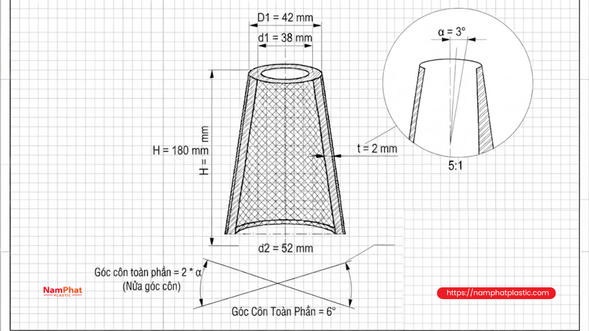
The taper angle represents the change in core diameter along its length. In technical terms, it is necessary to distinguish between:
- Half taper angle: the angle between the tapered surface and the centerline of the core.
- Included taper angle: the angle formed by two opposing tapered surfaces, normally twice the half taper angle.
This is an easily misunderstood point when ordering cores. One supplier may specify the half angle while another specifies the included angle. If both sides use the same numerical value without defining which angle is meant, the resulting core may be incorrectly manufactured.
For a taper length L, large diameter D2, and small diameter D1, the half taper angle can be determined geometrically as:
α = arctan[(D2 − D1)/(2L)]
This formula can be applied to either the internal or external taper, depending on which diameter set is being used.
Historical technical standards for tapered winding packages specified several different half-angle configurations, such as 3°30′, 4°20′, and 5°57′. This shows that taper angle is a defined design parameter and should not simply be estimated visually. Some of these standards have since been withdrawn by ISO, so they should be treated as technical references rather than automatically applied requirements for every type of thread spool.
4. Distinguishing the internal taper angle from the external taper angle
When referring to the “taper angle of the core,” it is necessary to specify which surface is being discussed.
Internal taper angle
This is the surface that contacts the support post, mandrel, or spool holder. It directly affects:
- Whether the spool can be inserted.
- How deeply the spool can reach.
- The contact area between the core and holder.
- Self-centering.
- The degree of spool wobble or tilting.
For spool installation, the internal taper is generally the most important parameter.
External taper angle
This is the outer surface on which the thread is wound. It affects:
- The final shape of the thread package.
- Retention of thread layers at the ends.
- Thread capacity.
- The shape of the thread loop during axial unwinding.
- Clearance between the thread package and guiding components.
The external taper does not necessarily have to be identical to the internal taper because the wall thickness can vary along the core. Therefore, measuring only the external diameter is not sufficient to determine installation compatibility.
5. How each core dimension affects thread spool installation
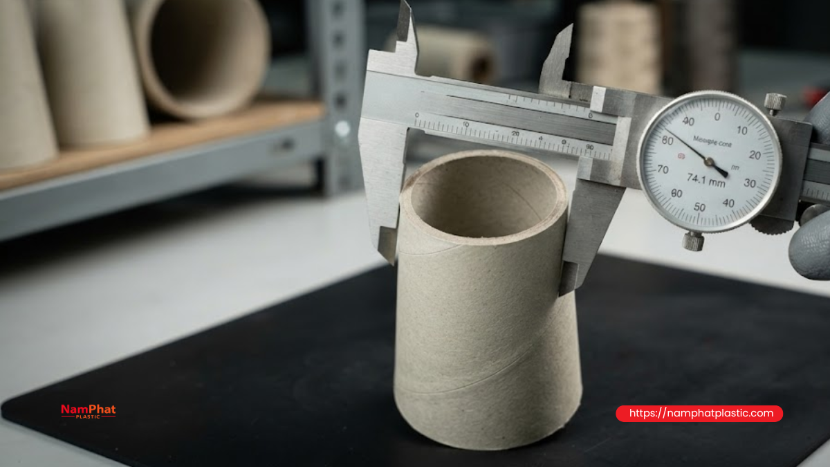
5.1. Small-end internal diameter
The small end is normally the first section to pass over the support post. If this diameter is too small, the spool may:
- Fail to fit.
- Enter only partially and then become stuck.
- Require twisting, pressing, or impact.
- Crack at the core edge.
- Remain above the intended position.
If the spool sits too high, the distance between the top of the spool and the thread guide changes. The unwinding loop may become larger or contact the holder, causing uneven tension.
Conversely, if the small-end internal diameter is too large, the upper portion loses part of its centering effect. The spool may tilt even though the bottom is still resting on the support disk.
5.2. Large-end internal diameter
The large-end internal diameter determines whether the core can reach the required depth and whether the lower section is properly supported.
If it is too small, the spool may stop before reaching the bottom. If it is too large, excessive clearance develops between the core and support post, allowing the spool to wobble laterally.
This becomes more obvious with heavier spools. A small clearance that causes little trouble with a lightweight spool may produce significant tilting when a 1–3 kg spool is subjected to vibration and thread-pulling forces.
5.3. Core length
Core length affects both mechanical stability and the thread path.
A core that is too short may:
- Have insufficient contact length with the support post.
- Tilt or wobble more easily.
- Fail to use the full height of the holder.
- Position the spool lower than intended.
A core that is too long may:
- Contact the thread guide or support frame.
- Leave insufficient clearance for top unwinding.
- Position the top of the spool too close to the thread guide.
- Interfere with the machine housing, protective cover, or automatic thread-delivery components.
Core length should therefore not be selected solely according to the desired thread capacity. It must also match the support-post length and available operating space.
5.4. Small-end external diameter
The small-end external diameter affects the top geometry of the thread spool. With top unwinding, the thread passes through this area before moving toward the thread guide.
If the core end is too large or the edge is too thick, the thread may:
- Rub against the core edge.
- Catch on burrs or loose paper layers.
- Experience intermittent pulling forces.
- Develop more fuzz, especially with spun PE or other staple-fiber threads.
If the end is too small or structurally weak, it may deform under winding pressure and destabilize the package surface.
5.5. Large-end external diameter
The large-end external diameter affects thread capacity, package-base dimensions, and support on the holder disk.
If it is too large, the spool may:
- Contact adjacent spools.
- Rub against the machine frame.
- Extend beyond the support disk.
- Cause the outer thread layers to contact surrounding components during unwinding.
If the core base is significantly smaller than the support disk, the spool may still be usable, but centering must be provided by the support post rather than relying only on the bottom surface.
5.6. Core wall thickness
A core that is too thin may:
- Become oval.
- Collapse under winding pressure.
- Crack when installed on a tapered post.
- Deform during stacking, humidity exposure, or transportation.
- Change its internal diameter after being fully wound.
A core that is too thick increases packaging weight, reduces available thread capacity, and may not fit the holder of the winding machine.
The objective is not to choose the thickest core, but to choose a wall thickness sufficient to maintain the required geometry during winding, transportation, storage, and use.
5.7. Roundness and concentricity
A core may have the correct average diameter but still be difficult to install if it is oval. In one direction, the core may be too tight; after rotating it 90 degrees, it may become too loose.
If the internal hole and external surface are not concentric, the thread spool can become offset from the support-post axis. The thread package may appear evenly wound while the entire spool is tilted relative to the thread path.
Concentricity is especially important for:
- Heavy thread spools.
- High-speed machines.
- Thread holders with short guide distances.
- Rotating shafts or precision winding chucks.
- Automatic thread-delivery systems with sensors or length measurement.
6. What problems can an unsuitable taper angle cause?
When the internal taper of the core matches the tapered support surface, the core tends to self-center and distribute contact forces over a relatively large area.
If the two taper angles do not match, contact may become concentrated near one end. Common consequences include:
The spool cannot reach the intended position
The core becomes trapped at a narrow contact area even though the core opening appears large enough. The operator may mistakenly think that the support post is dirty or that the core is simply too tight.
The spool wobbles even after reaching the bottom
The bottom of the spool contacts the support disk, but the internal tapered surface is not properly supported. The spool may wobble around the contact point, particularly when the thread is pulled sideways.
Concentrated pressure can crack the core
When installation force is concentrated over a narrow contact ring, local stress increases. Paper cores may delaminate, while plastic cores may develop whitening, cracks, or deformation.
The spool becomes difficult to remove
A core forced onto an incompatible tapered surface may become tightly locked. Vibration and environmental temperature changes can make the problem more noticeable.
Installation height varies between spools
Spools from the same batch may stop at different depths if taper angle, roundness, or internal diameter is inconsistent. This changes the position of the package top and consequently changes the thread-unwinding path.
7. The thread delivery method determines how important core dimensions are
Not every machine uses a thread spool in the same way. Before designing or ordering a core, the exact spool-mounting method should be identified.
7.1. Stationary spool with thread unwinding over the top
This configuration is common on many industrial sewing and bag-closing machines. The spool remains essentially stationary while the thread is pulled over the top.
In this configuration:
- Centering helps maintain a balanced thread-unwinding path.
- Installation height affects the distance from the spool to the thread guide.
- The top diameter affects the unwinding loop.
- Core-edge smoothness affects the risk of thread rubbing.
- Base stability prevents the spool from tilting or shifting.
JUKI technical documentation notes that an incorrectly positioned spool-retaining disk can create excessive tension when thread is pulled from a tapered spool. This shows that the spool position and holder geometry can affect thread tension, not just the tension device on the sewing machine head.
7.2. Spool rotating around the support post
In some systems, the thread is pulled tangentially, causing the spool to rotate. In this configuration, the clearance between the core and support post becomes more important.
If the fit is too tight:
- The spool rotates with greater resistance.
- Friction increases.
- Thread-pulling force increases.
- Stick-slip behavior may occur.
If the fit is too loose:
- The spool runs out.
- The core hits the support post.
- Rotation becomes unstable.
- The thread may move outside the intended guide path.
This type of mounting may require a properly designed bushing, retaining ring, or braking mechanism rather than simply placing the spool freely on a small post.
7.3. Installation on a mandrel or winding-machine chuck
For twisting, winding, or rewinding machines, the core may be held by a tapered shaft, expanding chuck, or clamping jaws. In this case, internal dimensions and taper angle need tighter control because they affect:
- Torque transmission.
- Runout.
- Winding-layer quality.
- Core removal.
- Core slippage on the shaft.
- Package geometry.
A core that is suitable for a stationary thread holder is not necessarily suitable for a winding-machine mandrel. Therefore, the same core drawing should not automatically be used for every production stage without actual testing.
8. Why can a misaligned core cause thread tension fluctuations?
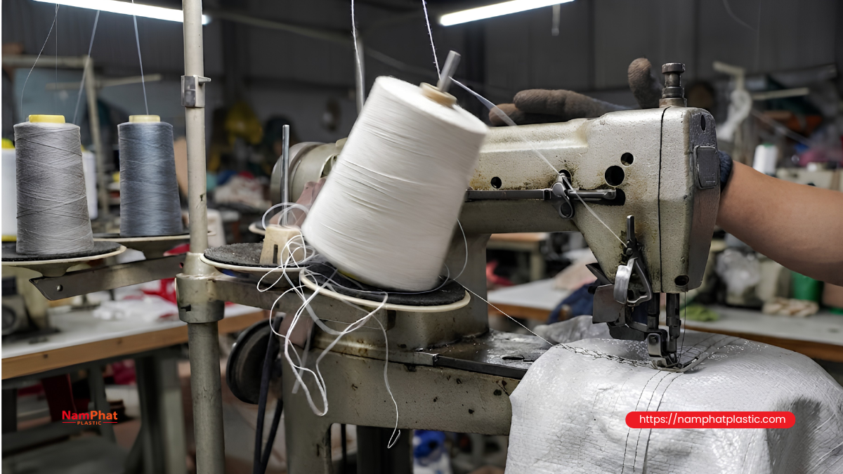
When thread is unwound over the top of a spool at high speed, the free thread section forms a moving loop commonly known as a balloon.
The shape and stability of this loop depend on several factors:
- Withdrawal speed.
- Thread mass and stiffness.
- Current spool diameter.
- Height and position of the thread guide.
- Package surface geometry.
- Friction at contact points.
- Alignment of the spool axis.
Studies of yarn unwinding show that thread tension is influenced not only by the spool surface but also by friction at guiding points. Therefore, when a core causes the spool to sit in the wrong position, the thread path and contact angle can change, which can also change the actual tension.
If the spool is tilted, the unwinding loop does not develop symmetrically around the axis. The thread may move closer to one side of the core or support frame. Each contact can create a short tension peak.
These peaks can contribute to:
- Random thread breakage.
- Skipped stitches.
- Inconsistent stitch tightness.
- Increased thread fuzz near the needle.
- Uneven thread withdrawal.
- Thread wrapping around the support post or holder.
Because the problem occurs intermittently, operators may try to solve it by adjusting the machine tension. However, if the actual cause is the core or spool position, reducing thread tension may only mask the symptom and may make the seam too loose.
9. Troubleshooting table for core-dimension and taper-angle problems
| Symptom | Possible core-related cause | How to check |
| Spool cannot enter the support post | Small-end ID too small, deformed core | Measure the internal diameter in several directions |
| Spool enters partially and then stops | Incorrect taper, large-end ID too small | Check contact marks on the support post |
| Spool does not reach the bottom | Internal hole too tight or support-post length unsuitable | Test with an empty core |
| Lateral spool wobble | Internal hole too large, incorrect taper, oval core | Gently move the spool and measure clearance |
| Spool sits at an angle | Poor concentricity, unevenly cut end, uneven support disk | Check with a square or observe while rotating |
| Core cracks during installation | Excessive interference, weak wall, concentrated contact | Inspect the crack and contact location |
| Thread rubs against the core mouth | Rough edge, package too close to the guide | Observe the thread path at low speed |
| Thread tangles around the holder | Misaligned spool, unsuitable guide clearance, excessive unwinding loop | Record the thread path in slow motion |
| Tension varies between spools | Inconsistent dimensions or installation height | Compare the seating depth of multiple spools |
| Core is difficult to remove from winding shaft | Incorrect taper, deformed core, excessive interference | Inspect contact surface and ovality |
10. How to measure thread-core dimensions accurately
Step 1: Identify the correct spool mounting method
First determine whether the spool is:
- Stationary on a holder.
- Free to rotate around a support post.
- Clamped on a rotating shaft.
- Held by an expanding chuck.
- Supported by a disk while the post only provides centering.
The mounting method determines which dimensions require the tightest tolerance.
Step 2: Measure core length
Measure along the core axis at multiple positions. If the two core ends are not parallel, measuring at only one point may fail to detect an angled cut.
Step 3: Measure internal diameter at both ends
Do not measure only directly at the edge because the edge may be flared, compressed, or burred. Measure:
- At the small end.
- At the large end.
- At a specified distance from the edge.
- In at least two perpendicular directions.
The difference between the two directions helps identify ovality.
Step 4: Measure external diameter
The external diameter should be measured at the same reference planes as the internal diameter. This helps determine wall thickness and calculate the taper angle more accurately.
Step 5: Calculate or verify the taper angle
Use the actual measured length and diameter difference. The drawing should clearly specify:
- Whether the angle is the half angle or included angle.
- Whether the angle applies to the internal or external surface.
- Where the diameter measurements are taken.
- Whether the unit is decimal degrees or degrees-minutes.
Step 6: Check straightness and concentricity
The core can be placed on a reference shaft and rotated slowly. Noticeable movement at the core end may indicate that the core is bent or that the internal hole is not concentric with the external surface.
For routine production inspection, a reference gauge shaft can be manufactured according to the actual machine-holder dimensions. An acceptable core should slide onto the gauge by hand, reach the specified reference position, and remain within the allowable wobble level established during machine trials.
11. Why tolerance should not be specified as one common value for every machine
Many manufacturers want to use a single tolerance, such as ±0.5 mm, for every core dimension. This approach may not be appropriate.
Tolerance should be based on:
- Actual support-post diameter and length.
- Cylindrical or tapered support post.
- Stationary or rotating spool.
- Spool weight.
- Paper or plastic core.
- Humidity conditions.
- Machine speed.
- Deformation after winding.
- Handling and removal requirements.
A 0.5 mm deviation on a large core may be insignificant, but on a short mounting section or small support post, it can create a relatively large clearance. Conversely, an excessively tight tolerance for paper cores can increase rejection rates without necessarily improving machine operation.
A more suitable approach is to:
- Measure the support posts of the machines actually being used.
- Establish an initial clearance range.
- Produce sample cores.
- Wind test spools.
- Run them at different speeds.
- Adjust the dimensions.
- Finalize tolerances based on actual test results.
12. Procedure for testing spool installation before mass production
Test with an empty core
An empty core helps separate the effect of core dimensions from thread weight and package geometry. The core should:
- Install by hand.
- Require no impact tool.
- Reach the specified position.
- Not become tightly locked.
- Not wobble excessively.
- Be removable after installation.
Test with a fully wound spool
After winding the specified thread weight, check again because winding pressure can change core dimensions.
Observe:
- Whether the spool still reaches the correct depth.
- Whether the core has deformed.
- Whether the spool remains upright.
- Whether the spool base is evenly supported.
- Whether it contacts the holder or adjacent spools.
Run the machine at different speeds
The spool should be checked at low, medium, and production speeds. It should not be judged after only a few stitches at low speed.
During testing, observe:
- Spool vibration.
- Unwinding-loop behavior.
- Contact between thread, core, and holder.
- Abnormal noise.
- Input thread tension.
- Thread-breakage or skipped-stitch frequency.
- Performance as the spool diameter decreases.
Test different spool states
A spool may operate well when full but develop problems near the end. As the thread layer diameter decreases, the distance between the unwinding surface and the thread guide changes, while more of the core becomes exposed.
At minimum, evaluate:
- Full spool.
- Approximately half-full spool.
- Nearly empty spool.
13. Are there differences between paper and plastic cores in terms of installation?
Paper cores
Paper cores offer reasonable cost, good thread grip, and easy disposal or handling after use. However, paper cores are more sensitive to:
- Humidity.
- Winding pressure.
- Transportation impact.
- Improper stacking.
- Edge deformation.
A paper core that meets dimensional requirements before winding may not retain exactly the same dimensions after winding and storage. Therefore, the finished package should also be inspected.
Plastic cores
Plastic cores generally provide better dimensional stability and moisture resistance. However, they can still experience:
- Shrinkage after molding.
- Warping caused by uneven cooling.
- Burrs at the mold parting line.
- Slippage on the holder if the surface is too smooth.
- Cracking when brittle plastic or excessive clamping force is used.
Choosing a plastic core does not automatically solve installation problems. Both paper and plastic cores require appropriate drawings, tolerances, and inspection procedures.
14. Specific considerations for PE and PP bag sewing thread spools
PE 20/6, PE 20/8, PE 20/9 and PP multifilament bag sewing threads are commonly used in continuous production environments where spool weight can be relatively high and thread withdrawal speed can be substantial.
Under these conditions, even a small core deviation can be amplified by:
- Spool weight.
- Continuous thread-pulling force.
- Machine and table vibration.
- Bag-closing speed.
- Spool changes between different machines.
- Custom-made or worn spool holders.
Even with the same thread type, changing the spool weight can change the requirements for the core. A heavier spool requires a sufficiently stable base and support post, while a larger spool requires more clearance around the thread-unwinding path.
When supplying bag sewing thread to multiple customers, manufacturers should collect at least:
- A photo of the spool holder.
- Support-post diameter.
- Support-post length.
- Whether the post is cylindrical or tapered.
- Distance to the first thread guide.
- Weight of the customer's current spool.
- Thread-unwinding direction.
- Machine speed.
- Current core sample, if available.
A core should not be described as suitable for “all bag sewing machines” simply because it works on one machine at the manufacturer's factory.
15. Parameters that should be included in the thread-core specification sheet
| Parameter group | Required information |
| Material | Paper, PP plastic, or other plastic |
| Core length | Nominal dimension and tolerance |
| Small-end internal diameter | Measurement position and tolerance |
| Large-end internal diameter | Measurement position and tolerance |
| Small-end external diameter | Dimension and tolerance |
| Large-end external diameter | Dimension and tolerance |
| Internal taper | Clearly specify half angle or included angle |
| External taper | Clearly specify half angle or included angle |
| Wall thickness | Minimum value or range |
| Ovality | Maximum-to-minimum diameter difference |
| Concentricity | Inspection requirement or reference gauge |
| Edge condition | No cracks, burrs, or delamination |
| Color or marking | Identification of each core type |
| Applicable spool weight | Tested operating range |
| Applicable machine type | Stationary holder, rotating shaft, or expanding chuck |
| Inspection method | Caliper, gauge, or machine trial |
Simply specifying “tapered paper core” or “standard plastic core” is not sufficient to control compatibility.
16. How to handle customer complaints that the thread spool does not fit the machine
When a customer reports that a spool does not fit, the entire core should not immediately be changed to a larger size. The exact failure mode should first be identified.
If the spool cannot be inserted
Ask the customer to provide:
- Support-post diameter.
- Core opening diameter.
- Photo of the point where the spool becomes stuck.
- A sample of the current core that works correctly.
If the spool can be inserted but does not reach the bottom
Check the taper angle, large-end internal diameter, internal deformation, and support-post length.
If the spool wobbles
Do not simply reduce the core diameter. Determine whether the support post provides centering or whether the spool is positioned by a disk, retaining ring, or bushing.
If the machine begins breaking thread after changing the core
Compare:
- Top height of the spool.
- Distance to the thread guide.
- External spool diameter.
- Core-edge smoothness.
- Spool inclination.
- Thread-unwinding direction.
- Winding-package geometry.
Changing the core can alter the thread path even when the thread itself retains the same strength and twist.
Frequently Asked Questions about core dimensions and taper angle
1. Is a wider core hole always easier to install?
No. An excessively wide hole makes installation easier but can cause the spool to wobble, tilt, or lose concentricity. The objective is to provide an appropriate clearance, not the largest possible hole.
2. Can an adapter or bushing be used to compensate for an oversized core?
Yes. An adapter or bushing can be used if it is properly designed and remains concentric and securely fixed. Paper, cloth, or other soft materials should not be inserted arbitrarily because they can shift during operation.
3. Is concentricity still important if the spool remains stationary?
Yes. Even when the spool does not rotate, the thread moves around the spool surface during unwinding. A tilted spool changes the thread path and the distance to the thread guide.
4. Does the external taper determine whether the spool fits the support post?
Not completely. Installation compatibility mainly depends on the internal diameter and internal taper. The external taper has a greater influence on spool shape and thread unwinding.
5. Why does an empty core fit while the finished spool does not?
Winding pressure, humidity, temperature, and storage conditions can deform the core. Therefore, both the empty core and the fully wound spool should be checked.
6. Is there one standard core size that can be used for all bag sewing machines?
There is no single configuration that is universally compatible with every holder and machine. A common size can be developed for a specific target group of machines, but actual equipment testing or a suitable adapter is still required.
Conclusion
Core dimensions and taper angle do not only determine whether a thread spool can be inserted onto the support post. They also affect installation depth, spool alignment, self-centering, distance to the thread guide, and unwinding stability.
A suitable core should be controlled for:
- Internal diameter at both ends.
- Core length.
- Internal and external taper angle.
- Roundness.
- Concentricity.
- Wall thickness.
- Dimensional stability after winding.
- Compatibility with the actual spool holder.
For industrial bag sewing thread, especially spools used continuously on packaging lines, proper core control can help eliminate a group of problems that are often mistakenly attributed to thread quality. Instead of checking only whether the spool “fits,” manufacturers should evaluate the complete process from spool installation and centering to thread unwinding until the spool is nearly empty.
Nam Phat Plastic manufactures and supplies PE and PP bag sewing threads according to requirements for specifications, spool weight, and core type. Confirming the core sample, holder dimensions, and actual machine operating conditions before mass production helps improve spool compatibility with each customer's equipment.
>>> See more:
- 0 Comment


