


 Phan Van Hoang
- 21/10/2026
- 3
Plastic injection molding machines shape products by injecting molten plastic into a mold, applying holding pressure, and allowing the part to cool before removal. The process is used to manufacture basins, buckets, chairs, containers, components, and pallets from materials such as PP, PE, ABS, and engineering plastics selected for the application.
However, a thin-wall container and a load-bearing pallet present very different engineering challenges. Choosing a machine solely by its clamping tonnage or shot weight can overlook injection speed, mold dimensions, and cooling capacity. A more effective evaluation follows the sequence product → material → mold → machine → cost per acceptable part.
Table of Contents [Hide]
1. How does a plastic injection molding machine work?
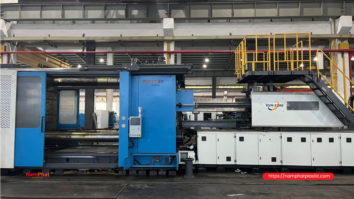
A thermoplastic injection molding system typically includes a plasticizing and injection unit, a clamping unit, a controller, a mold, and auxiliary equipment. The screw rotates to convey and plasticize the material. During injection, it moves forward to push the prepared melt into the mold.
- Mold closing and clamping: The two mold halves are held closed against the opening force generated by melt pressure.
- Filling: Melt passes through the nozzle, runner system, and gate into the mold cavity.
- Holding pressure: Additional material compensates for volumetric shrinkage while the gate can still transmit pressure effectively.
- Cooling: The part becomes sufficiently rigid for removal without excessive deformation. Material preparation for the next shot can often take place during this stage.
- Mold opening and part removal: An ejector system or robot removes the part, and the next cycle begins.
When analyzing cycle time, account for operations that can overlap. Do not count plasticizing time twice if plasticizing is completed during cooling. Conversely, if plasticizing is not complete when the part is ready for removal, the injection unit becomes a production bottleneck.
2. Selecting PP, PE, and ABS to match product requirements
The polymer name is only the first level of classification. Two PP grades can differ substantially in flow behavior, stiffness, impact resistance, and intended applications. Similarly, not every PE grade is suitable for pallets or rigid containers. Identify the specific injection molding grade required.
| Material | Potential applications | Points to verify |
|---|---|---|
| PP | Basins, buckets, chairs, containers, lids, and certain pallets | Balance of stiffness and impact resistance; flow properties; long-term deformation; hinge requirements, if applicable |
| HDPE | Buckets, bins, tough components, and appropriately designed pallets | Stiffness, shrinkage, environmental stress-cracking resistance, and chemical exposure conditions |
| LDPE/LLDPE | Flexible parts, lids, or components requiring flexibility, using suitable grades | Do not assume these materials can replace HDPE in load-bearing products or applications requiring high stiffness |
| ABS | Equipment housings, technical enclosures, and parts requiring a good surface finish and rigidity | Moisture, thermal stability, outdoor exposure requirements, and application-specific chemical resistance |
| PA, POM, PC, PBT, blends, or reinforced plastics | Components with specific thermal, frictional, mechanical, or dimensional requirements | Mold design, drying, injection-unit wear resistance, and grade-specific technical data |
Do not use melt flow rate as a complete measure of quality
MFR/MFI helps screen processing behavior, but it must be read together with the test temperature and load. Values measured under different conditions cannot be compared directly. Thin-wall containers may require easy-flowing materials, while chairs and pallets need a balance between flow, load capacity, impact resistance, and service durability. A lower resin price does not necessarily mean a lower finished-part cost if part weight or rejection rates increase.
Shrinkage and drying requirements are grade-specific
PP and PE are semicrystalline plastics. Shrinkage depends on the material, part geometry, cooling conditions, and holding pressure. A single shrinkage percentage should not be used to manufacture every mold. LyondellBasell's Mold Shrinkage guidance notes that data from simple test specimens is comparative and does not replace determining shrinkage for the actual mold.
Standard virgin PP and PE generally do not require dehumidifying drying in the way many engineering plastics do. However, condensation on pellets, regrind, fillers, and additives still need to be assessed. ABS generally requires drying according to the supplier's instructions. For example, INEOS Styrolution provides specific guidance for Terluran GP-22; this grade's parameters should not be treated as a universal recipe for ABS.
Food-contact containers require appropriate documentation covering the exact resin grade, colorants, additives, and intended conditions of use. The fact that a material is PP or PE does not, by itself, establish that the finished product is suitable for food contact.
3. Which specifications matter most for each product group?
| Product | Machine and mold selection priorities | Quality requirements to verify |
|---|---|---|
| Basins and buckets | Projected area, mold depth, part-removal stroke, and wall uniformity | Rim roundness, base stability, leak tightness, and strength of handles and their attachment points |
| Chairs | Large molds, long flow paths, rib distribution, and uniform cooling | Leg stability, load capacity, and impact resistance under defined test conditions |
| Thin-wall containers | Injection rate, acceleration response, cavity balance, and rapid part removal | Complete filling, consistent weight, lid sealing, and stackability |
| Components | Shot repeatability, temperature control, positioning, and assembly tolerances | Dimensions after stabilization, weld-line strength, and actual functional performance |
| Pallets | Clamping force, shot volume, mold weight, opening clearance, and robot integration | Static, dynamic, and racking loads; deflection; and impact resistance |
Thin-wall containers demonstrate why sufficient shot capacity does not automatically mean efficient molding. The material must fill the cavity before excessive freeze-off restricts flow. ENGEL's thin-wall injection molding solutions emphasize injection-unit dynamics and plasticizing performance for this application.
For pallets, purchasing specifications must define the type of load, whether the pallet is supported on the floor or in racking, the service temperature, and the loading duration. A load rating without test conditions is insufficient for selecting the material, design, or machine. For chairs, resin tensile-strength data cannot replace testing the complete product. Pallets may be molded in one piece or assembled from separately molded parts; shot sizing must be based on the part actually molded in each cycle, not automatically on the weight of the completed pallet.
4. Calculating clamping force: projected area matters more than weight
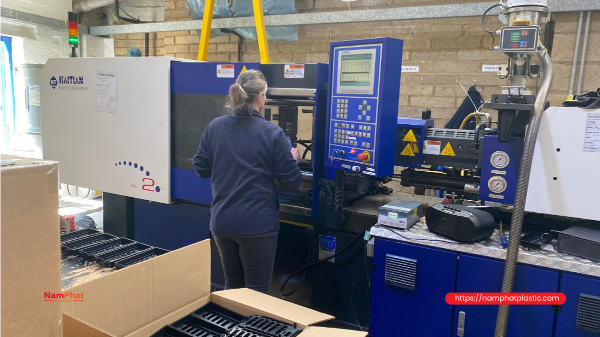
Clamping force keeps the two mold halves closed. Injection pressure drives the melt through the flow channels and into the cavity. These quantities have different functions and units: clamping force is usually expressed in kN or tonnes-force, while injection pressure is generally expressed in bar or MPa.
For a preliminary estimate, consider the projected area of all cavities and those portions of the runner system that contribute to mold-opening force in the clamping direction. The pressure used is an equivalent cavity pressure for the loading case being assessed, not automatically the maximum injection pressure stated in the machine catalog.
F (kN) = A (cm²) × P (MPa) × 0.1
Where 1 MPa = 1 N/mm²; 1 cm² = 100 mm²; 1 metric tonne-force ≈ 9.80665 kN.
Illustrative example: Assume a total projected area of 600 cm² and an equivalent cavity pressure of 35 MPa. The estimated opening force is 600 × 35 × 0.1 = 2,100 kN, or approximately 214 tonnes-force. If the engineering team selects an illustrative allowance factor of 1.15, the preliminary requirement becomes 2,415 kN, or approximately 246 tonnes-force.
This example does not mean that every product with a projected area of 600 cm² can be molded on a 250-tonne machine. Actual pressure also depends on wall thickness, flow length, gate position, material, and filling conditions. A machine that satisfies the calculation must still pass mold-compatibility checks, injection-unit checks, and trials. For a reference on projected area and the limitations of estimation, see Kruger Industries' clamping-force guide.
5. Checking shot capacity, screw specifications, and mold compatibility
Do not interpret “grams of PS” as grams of every plastic
Catalogs may specify shot volume in cm³ and shot weight based on PS. The stated PS weight must not be used directly as the machine's shot capacity for PP, PE, or ABS. Determine the total material required for every part in one cycle, plus the sprue and cold runners, then compare this requirement with usable volume, melt density, and the manufacturer's conversion guidance.
For hot-runner systems, do not count all the material inside the manifold as material discharged on every cycle. However, the melt held in the system still affects residence time, color changes, and degradation risk. ARBURG's technical data sheet clearly illustrates the separate reporting of swept volume, PS shot weight, injection rate, and injection pressure.
An undersized injection unit may lack shot capacity or fail to plasticize material quickly enough. An oversized unit used for very light parts can cause excessive residence time. Covestro's injection molding equipment guidance identifies residence-time risks when the metering stroke is too short. Buying a much larger machine for spare capacity is therefore not always the safest choice.
Read the full specification set, not a single column
- Screw diameter: Affects volume per unit of stroke; changing the diameter can also change the available injection pressure.
- Injection rate, cm³/s: Useful for comparing filling requirements. Forward screw speed in mm/s can only be compared meaningfully when screw diameter is known.
- Injection and holding pressure: Check continuous operating limits, not only peak values. Maximum injection pressure and maximum injection rate may not be achievable simultaneously; check the operating envelope of the actual configuration.
- Plasticizing capacity: Compare using the specified material and test conditions. A kg/h rating based on PS does not automatically represent PP output.
- Screw and barrel materials: Assess suitability for reinforced plastics, fillers, or compounds requiring wear or corrosion resistance.
The mold must fit, and the part must be removable
The compatibility review should cover tie-bar spacing where applicable, platen dimensions, minimum and maximum mold thickness, opening stroke, maximum daylight, permissible mold weight, and ejector stroke. Also check mounting-hole positions, locating ring, nozzle compatibility, core-pull mechanisms, and robot interfaces.
For deep buckets or large chairs, a mold may fit on the platens while still leaving insufficient clearance to remove the part. The layout drawing must therefore account for the part, gripper, and movement path, not just the closed mold's external dimensions.
6. Hydraulic, electric, or hybrid: compare against the actual application
| Drive type | Potential considerations | What to verify before selection |
|---|---|---|
| Hydraulic, including servo-hydraulic | A wide range of configurations; convenient integration of hydraulic functions, depending on the design | Energy consumption during the actual cycle, oil and heat management, repeatability, and maintenance |
| Electric | Direct axis control; suitable for repeatability and rapid-motion requirements when appropriately configured | Injection and holding-pressure limits, mold loads, auxiliary core-pull equipment, and lifecycle cost |
| Hybrid | Combines electric and hydraulic axes to meet specific requirements | Which axes are electric and which are hydraulic, and whether simultaneous movements are supported |
Do not assume that electric machines always save a fixed percentage of energy, or that hybrid machines are faster than every hydraulic machine. The specific configuration and product cycle determine the result. ARBURG describes hybrid machines as combining electric and hydraulic axes; the term does not denote one universal configuration.
During trials, record energy consumption per acceptable part and define the measurement boundary: the machine alone or the machine together with the chiller, dryer, and robot. Comparing the same mold, material, quality requirements, and operating conditions is more useful than comparing installed motor power.
7. Molds and auxiliary equipment determine process stability
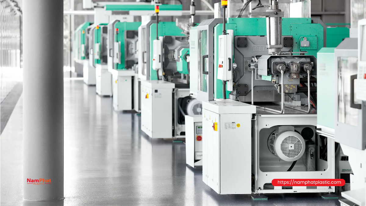
A good machine cannot compensate for every design weakness. Gate design must account for filling location, permitted gate marks, and weld lines, while multiple cavities must be balanced. Venting must be designed and maintained to minimize trapped gas. Do not modify vents using one standard dimension for all plastics.
Cooling requires control of both temperature and flow rate in each circuit. A chiller with sufficient nominal capacity does not guarantee effective mold heat transfer if channels are blocked or flow distribution is uneven. Monitor temperature differences and flow conditions to distinguish problems in the cooling supply from problems inside the mold.
- Material feeding and dosing: Reduce the risk of mixing incorrect grades, incorrect colorant ratios, or inconsistent material feeds.
- Dryers: Select technology appropriate to the resin and assess the moisture level achieved, rather than relying only on the displayed temperature.
- Mold temperature controllers: Maintain the required thermal conditions, which does not mean making the mold as cold as possible.
- Robots and conveyors: Coordinate with the cycle, minimize deformation during gripping, and avoid delays at the stacking stage.
- Granulators: Control particle size, dust, contamination, and scrap traceability before considering reuse.
Even clean in-house regrind is not automatically equivalent to virgin resin. Reuse ratios must be validated against customer requirements, product function, and material documentation. Sensitive applications require a separate assessment rather than reliance on a default percentage.
8. Troubleshoot defects using evidence, not guesswork
When a defect appears, first retain samples and establish whether it affects every cavity or only one location, and whether it occurs continuously or after a batch change. Then compare material information, cycle data, and mold condition. The table below helps narrow down potential causes; it is not a set of instructions to increase or decrease machine settings directly.
| Defect | Potential cause categories | Evidence to collect |
|---|---|---|
| Short shots | Filling capability, material feed, gates, and trapped gas | Unfilled locations, part weight, pressure traces, and filling time |
| Flash | Parting surfaces, clamping load, cavity pressure, and mold wear | Flash locations, surface condition, and cycle-to-cycle repeatability |
| Sink marks or voids | Material accumulation, shrinkage compensation, and pressure transmission through the gate | Cross sections, local wall thickness, and part weight after holding |
| Warpage | Uneven shrinkage, cooling, flow orientation, and demolding | Dimensions over time, mold temperature, and deformation direction |
| Silver streaks or burn marks | Moisture, gas, degradation, or thermal history | Moisture content, material batch, defect location, and residence time |
| Weak weld lines | Meeting flow fronts, bonding conditions, design, and material | Weld-line locations and mechanical or functional testing |
BASF's injection molding troubleshooting guide can serve as an initial reference. Conclusions should be based on production-line inspection and controlled trials. Changing several factors at once makes the true cause harder to identify.
The quality plan should include start-of-shift samples, samples after material-batch or mold changes, visual acceptance criteria, and critical dimensions. For assembly components, agree on the time after molding at which measurements are taken and on sample-conditioning requirements. A part that meets dimensional specifications immediately after demolding is not necessarily stable when assembled.
9. Calculating output and cost per acceptable part
Theoretical hourly output = 3,600 × number of parts per cycle ÷ cycle time in seconds. Production planning must account for downtime, speed losses, and scrap, while avoiding double-counting losses already included in measured data.
Illustrative example: A two-cavity mold with a 30-second cycle produces a theoretical 240 parts/hour. If productive running time is 85% and the acceptance rate is 98%, expected acceptable output is 240 × 0.85 × 0.98 ≈ 200 parts/hour. This calculation assumes the actual cycle remains 30 seconds while the machine is running.
Costing should allocate actual material consumption, electricity and utilities, labor, depreciation, maintenance, tooling, inspection, and packaging across acceptable output. Do not multiply output by cavity count while ignoring blocked-off cavities or rejected parts.
Adding cavities can increase output, but it also makes the mold larger, increases shot-capacity requirements, and makes balancing more difficult. Reducing cooling time is useful only if the parts still meet requirements after stabilization. If the robot or packaging operation is slower than the machine, investing in a higher injection rate may not increase shipped output.
10. Information to prepare before requesting a machine configuration
- Product drawings or samples, dimensions, target weight, and critical tolerance areas.
- Proposed resin grade, color, additives, and recycled-material requirements, if any.
- Monthly production volume, number of shifts, batch sizes, and color-change frequency.
- Mold drawings, cavity count, dimensions, weight, and special mechanisms.
- Acceptance criteria for appearance, dimensions, function, cycle time, and acceptance rate.
- Electricity, water, compressed air, foundations, space, lifting equipment, and maintenance arrangements.
Request trials using representative products and retain the test conditions. A good-looking sample produced over a few cycles is insufficient to demonstrate stable production. When comparing quotations, separate the machine, mold, auxiliaries, robot, installation, training, warranty, and spare parts so that the quoted scopes are comparable.
11. Safe operation of plastic injection molding machines
Do not remove, disable, or bypass guards and safety interlocks. During maintenance or work in hazardous areas, follow the site's energy-isolation and lockout/tagout procedures together with the manufacturer's instructions. Opening a safety gate does not replace the complete energy-isolation procedure.
Control hazards from hot surfaces, molten plastic, stored pressure, and robot movement. Personnel must be trained and provided with suitable protective equipment and ventilation appropriate to the materials in use. Refer to OSHA's safety guidance for horizontal injection molding machines as a technical reference; it does not replace the legal requirements and safety procedures applicable at the factory.
Frequently asked questions about plastic injection molding machines
1. Can one machine process PP, PE, and ABS?
Yes, provided the machine configuration, plasticizing unit, temperature range, and auxiliary equipment meet each material's requirements. Appropriate material-changeover, cleaning, and drying procedures are still necessary. Using the same machine does not mean using the same mold or copying all process settings.
2. How much clamping tonnage is needed for basins, buckets, and chairs?
The product name alone is not enough to determine this. Projected area, cavity count, anticipated cavity pressure, and flow design are required. After estimating clamping force, shot capacity, mold dimensions, and part-removal stroke must also be checked. Finished-part weight addresses only part of the selection process.
3. Why can a machine with sufficient shot capacity still struggle with thin-wall containers?
The machine may lack the injection rate or acceleration required during filling. Mold design, venting, and resin grade can also restrict flow. Assess the injection unit and product design together rather than simply increasing maximum pressure.
4. Can recycled plastic be used to mold pallets?
It can be considered when the material and finished product have been assessed as suitable. Contamination, flow properties, strength, and batch-to-batch consistency must be controlled. Racking loads, temperature, and loading duration require specific testing; suitability cannot be inferred from a pallet's substantial appearance or weight.
5. Should purchase price or energy efficiency take priority?
Compare the total cost per acceptable part over the expected service life. A higher purchase price is justified only if benefits in output, energy consumption, quality, or maintenance offset the difference. Use trial data and transparent operating assumptions rather than an advertised savings percentage.
Conclusion: select the machine around finished-product requirements
The right plastic injection molding machine produces parts that meet requirements at an acceptable cost and with consistent performance. Whether manufacturing basins, buckets, chairs, containers, components, or pallets, start with the material and service conditions, then use data to verify the mold, clamping force, shot capacity, speed, and auxiliary equipment.
Explore more plastics industry knowledge from Nam Phát Plastic. For packaging and post-production product protection, see the PE bags and PE packaging category and discuss specifications, dimensions, and intended use with Nam Phát. This article provides information about injection molding technology; it is not an announcement that Nam Phát supplies injection molding machines or manufactures the injection-molded products discussed above.
- 0 Comment


